![]()
A Closer Look
 |
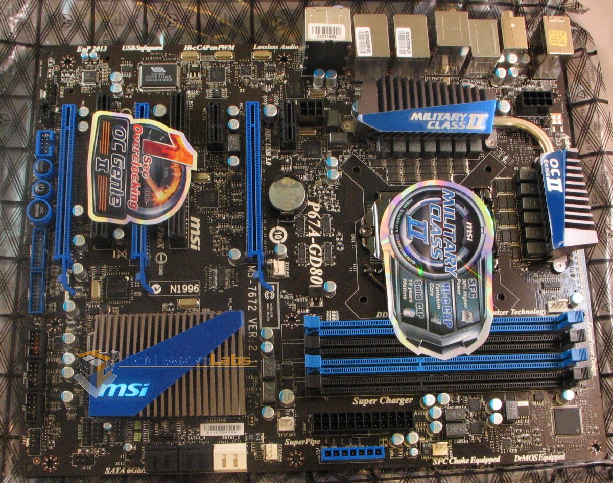 |
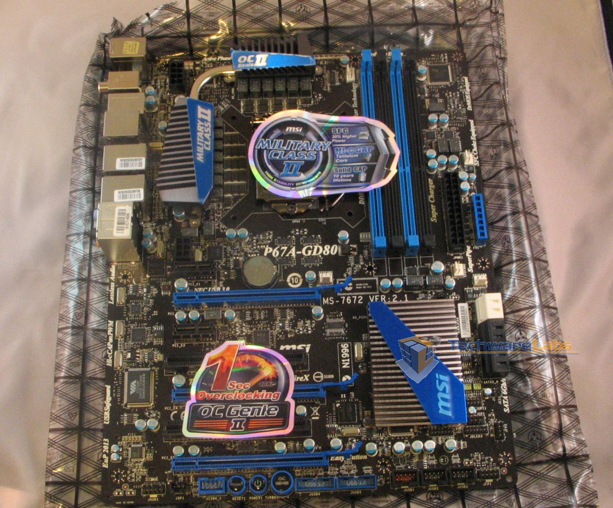
Overall, the board itself is very attractively laid out; the black-and-blue theme is quite tasteful. One thing that is immediately apparent is the attention paid to spacing–everything has its place, and none of it feels cramped or ill-placed.
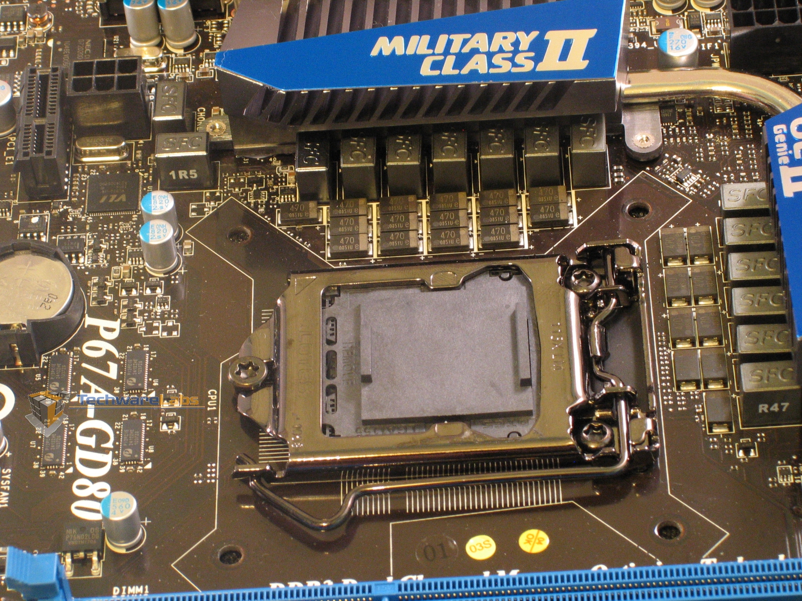
The area around the CPU socket is pretty clear, with the MOSFET heatsinks set well back. Do note the solid-state capacitors above and to the side of the socket; if you use an after-market cooler, you’ll need to be sure the mounting bracket doesn’t poke out too far on either side.
Just visible in the upper right of this photo is a 6-pin power plug. This isn’t required for operating the motherboard itself, but rather acts as an alternate way to supply extra power to a graphics card installed in the topmost PCIe x16 slot. An unusual addition to be sure, but quite welcome for those trying to make the best of the cable-routing situation in a tight case.

One thing to note here is how close the ram sockets are to the cpu; well within spec, but you’ll need to be careful if you have ram with tall heat spreaders and a large heatsink. The sockets themselves are helpfully color-coded to identify module pairings for dual-channel operation. Match blue with blue, black with black, and you’re good to go.
That blue socket next to the ATX power plug isn’t some fancy new I/O interface, it’s a set of voltage check points. This means that if you want to push your system to the edge with overclocking, or just do some diagnostics, you have the means to directly monitor CPU core voltage, CPU I/O voltage, CPU System Agent voltage (memory controller, DMI, PCIe controller, display engine), DDR voltage, and southbridge voltage. A set of short connector wires has even been provided for those times when sticking the multimeter probes straight in would be difficult.
Also worth noting here are the fan headers: five in all. One of them is a four-pin header reserved for the CPU fan, the rest are three-pin. All of them can be throttled automatically by the BIOS—handy for quieting your rig down when it’s not going full-tilt.
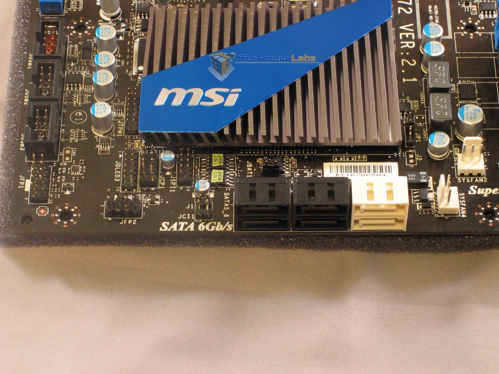
Moving over to the south end of the board, we see the SATA connectors. As with many enthusiast boards, the P67A-GD80 mounts the SATA ports edge-on. This not only makes cable hiding easier, it also lets you use the ports even with multiple full-length graphics cards plugged in. The two white ports provide SATA 6.0Gbps speed, while the four black ports provide SATA 3.0Gbps speed. Note that there are no IDE ports here, nor anywhere else on the board; if you’ve been hanging on to an old IDE optical drive, you’ll have to ditch it for this board. Also missing is anything resembling a floppy port—good riddance to that, I say. Cutting out those legacy ports allowed MSI to keep the front edge of the board mostly clear, and helped them avoid any awkward positioning of the ports that are present.
Also visible here are the front panel headers, the three USB 2.0 headers, and the southbridge heatsink. While the front panel headers don’t have pinouts silk-screened onto the board itself, the quick-connect plugs provided with the board have all the info you’ll need to get the pins lined up, and make the process of actually plugging the pins into the board much easier.
 |
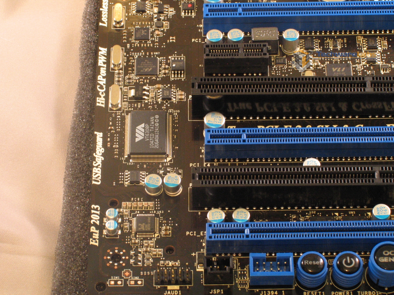 |
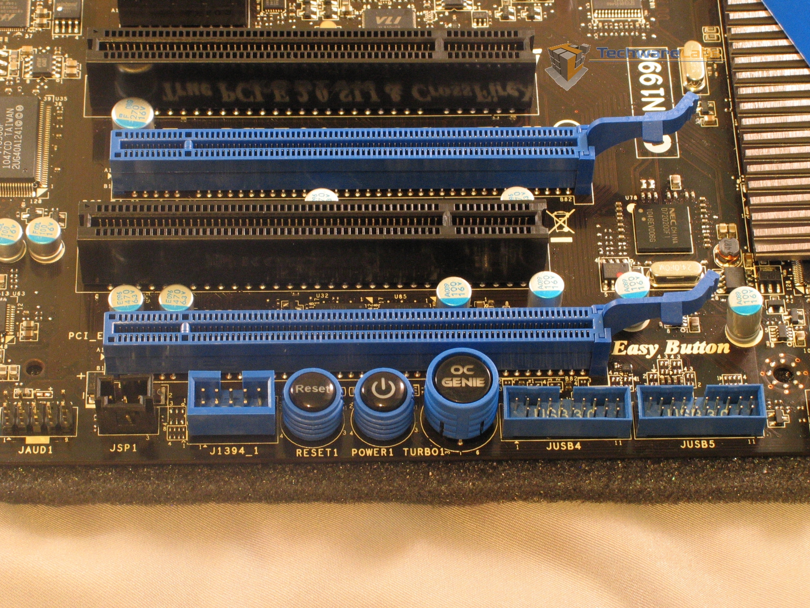
Back at the rear of the board, we see the expansion slots arrayed above yet more headers. This board provides three PCIe x16 slots, two PCIe x1 slots and two PCI-X slots. Using them all at once is a bit tricky however, due to chipset limitations. Installing two graphics cards cuts the lanes available to each down to x8, while the bottom x16 slot is only wired for x4. Actually installing an x4 card in the bottom slot shuts off the two eSATA ports, the two USB 3.0 front panel headers, the two PCI-X slots and one of the rear USB 3.0 ports. Clearly, three card SLI or Crossfire is not something to be undertaken lightly.
Looking down from the PCI ports, we see a lineup of buttons and headers. From the left: AZALIA front-panel audio, S/PDIF out, 1394/Firewire 400, reset button, power button, OC Genie button, and two USB 3.0 front panel headers. The OC Genie button deserves special mention; it allows the user to to toggle automatic overclocking on and off between reboots.

Swinging back up to the north end of the board, it’s obvious that the P67A-GD80 has no shortage of I/O ports. From the left we have a PS/2 keyboard/mouse port, two USB 2.0 ports, a Clear CMOS button for quickly resetting the BIOS to its default state, coaxial and optical S/PDIF audio out, a 1394/Firewire 400 port, two USB 3.0 ports, two more USB 2.0 ports, two eSATA ports, two gigabit Ethernet ports, four more USB 3.0 ports, and analog ports for the on-board surround sound audio.

[…] MSI P67A-GD80 Motherboard @ TechwareLabs […]
[…] TechwareLabs Evocarlos @ MSI forums *expect to see more reviews in the coming […]
[…] MotherboardsMSI P67A-GD80 @ TechwareLabs […]
[…] MSI P67A-GD80 Motherboard | TechwareLabs […]
[…] MotherboardsMSI P67A-GD80 @ TechwareLabs […]
[…] MSI P67A-GD80 Motherboard @ Techwarelabs […]
[…] by storm. MSI's swinging for the bleachers here, let's see if they hit a Grand Slam or a foul ball.http://www.techwarelabs.com/msi-p67a-gd80-motherboard/DiggLeave a Reply Click here to cancel reply. Name (required) Mail (will not be published) […]
[…] P67A-GD80 Motherboard – TechwareLabs […]