

|


![]()
Specifications:
| CPU |
|
| Front Side Bus |
|
| Chipset |
|
| Memory |
|
| Audio |
|
| LAN |
|
| Expansion Slots |
|
| Storage Interface | South Bridge:
|
| IEEE 1394a |
|
| USB |
|
| Internal I/O Connectors |
|
| Back Panel Connectors |
|
| I/O Controller |
|
| H/W Monitoring |
|
| BIOS |
|
| Unique Features |
|
| Bundle Software |
|
| Operating System |
|
| Form Factor |
|
I/O Panel:
Building upon the specifications above the picture below shows the I/O panel for the Gigabyte EP45T-Extreme. The sheer connectivity options on this board should easily meet or exceed the needs of most users.

Also shown in this view is the additionally provided bracket which gives you access to two eSATA ports and a molex power adapter. The inclusion of a CMOS clear switch on the I/O panel is extremely useful when overclocking as it makes life much easier than having to pop open the case panel and clear the CMOS via a jumper. Once again this is very befitting of the Extreme monniker.
What you can easily see from this view is the duall gigabit ethernet ports, your audio I/O, a total of 8 USB 2.0 rear ports, SPDIF as well as Coax, and your standard PS2 ports. We find the inclusion of PS2 ports rather redundant on motherboards these days but admit that there are still some manufacturers and consumers left in the dark ages of PS2. All in all, the I/O panel provides quite a bit of expandability and we haven't even touched on the layout of the motherboard yet.
Onboard Extreme Cooling:
Gigabyte has taken some extra steps to make sure that the EP45T-Extreme lives up to its name in the cooling department. Heatpipes and heatsinks made from copper carry heat away from sensitive areas and to top it off consumers who already own a water cooling system will find the EP45T Extreme comes with a water cooling compatible waterblock already installed on the chipset. Since the chipset waterblock employs heatpipes connecting several areas of thhe motherboard, simply attach two tubes frmo a water cooling system to the wateblock and you have essentially cooled the motherboard as well.
An overhead view shows the cooling system on the EP45T links the mosfets with the chipset in an almost S shaped configuration. The space that you see next to the chipset is used to mount an extention to the cooling system which allows for cool air to pass over the fins and help transport more heat away from the system. We do find it curious that no fan assists in this transport of air, as it seems the system was designed to be used exclusively with already present case fans. You may want to take this into consideration when assembling your system.
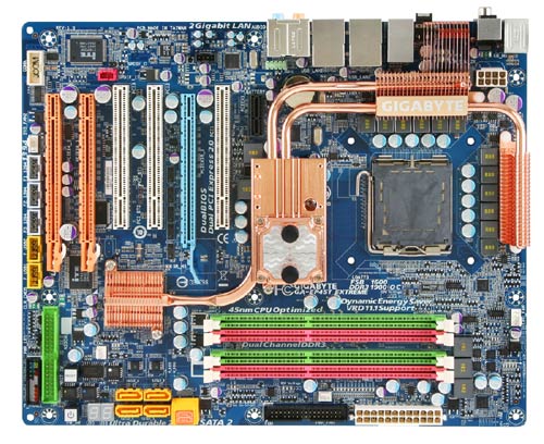
This overhead view is also ideal for analysis of the board layout. Component placement is one of the most important factors to ease of installation and maintenance of the system. DIYers and enthusiasts can attest that a good or bad motherboard layout can make or break a system in terms of functionality and use. A few important layout decisions become immediately apparant:
- (2) Two 90 degree SATA connectors are included with 4 standard straight SATA sockets.
- A single IDE connector is located at the bottom of the board.
- Color coded RAM slots designating channel A and B.
- (3) Three PCI-E x16 slots, (3) Three PCI slots, and (1) One PCI-E x1 Slot are available.
- Questionable location of the CMOS battery under the heatpipes will lead to difficulty in replacement.
- The cooling add-on may interfere with larger PCI cards placed in the top slot.
- Plenty of room around the CPU socket for installation of larger heatsinks.
Click to continue and take a look at installation and our test setup.