Packaging & A Closer Look
 |
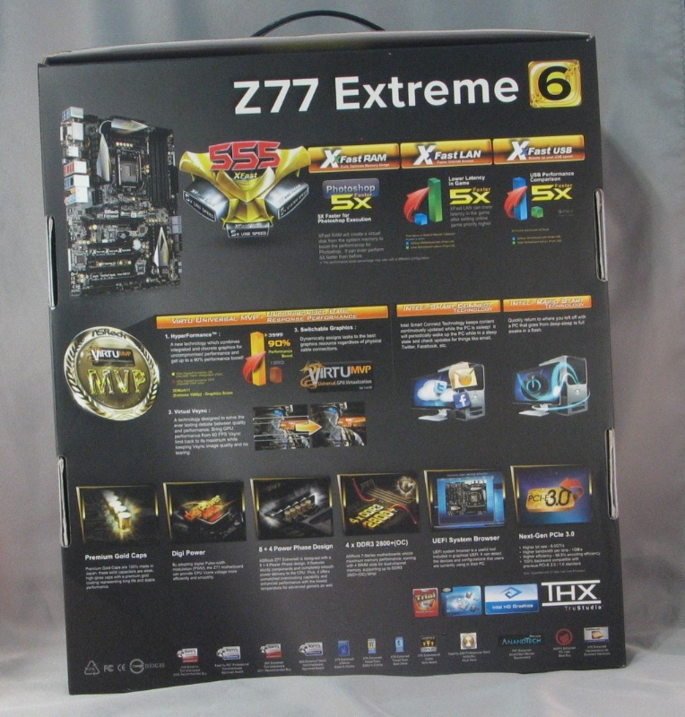 |
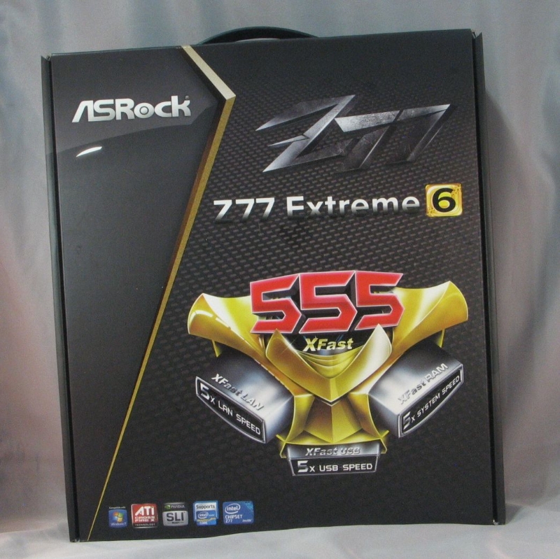
| Box front | Box rear |
 |
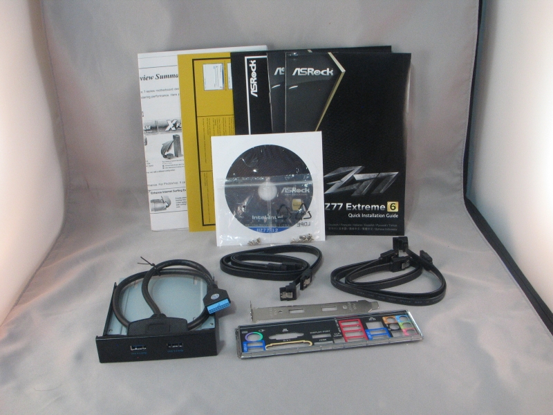 |
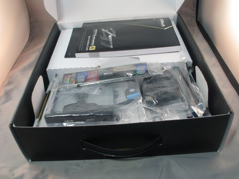
| Box open | Accessories |
Fairly standard packaging here. Aside from the standard manual, SATA cables, driver disc and IO backplate, this board comes with a USB3 port pair that runs off the header, and can be installed either in a 3.5″ drive bay or a expansion card slot. The ports are secured in either place with a couple of Phillips head screws, so changing it over is easy.
 |
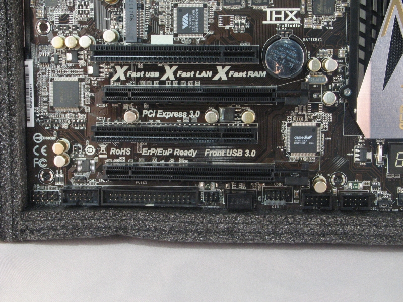
| Board overview |
The overall layout is fairly clean, with everything done up in a tasteful black, silver and gold color scheme. The board has four PCIe x16 slots, one wired for x16, one wired for x8, one wired for x4. If you’re planning on running a SLI or Crossfire rig, be aware that the x16 slot will downshift to x8 when a second graphics card is present in the x8 slot. Also present are two legacy PCI-X slots, one PCIe x1 slot, and one mini-PCIe slot. The 4-pin Molex plug above the top slot has to be plugged in to the power supply when two graphics cards are present, or it won’t boot.
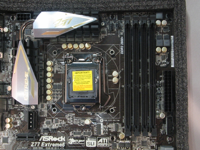 |
| CPU and RAM socket detail |
As with most LGA 1155 boards, clearance around the CPU socket is good. The ram sockets are rather close, so if you have an especially large cooler, you might have to be careful with vertical clearances. Above the socket itself, we see headers for two CPU fans–a helpful addition in these days of large, dual-fan CPU coolers. The second and third chassis fan headers are below the CPU socket, near the PCIe x1 slot. In an unusual fit of good sense, ASRock has placed the USB 3.0 header high on the front edge of the board, so your header cable doesn’t have to stretch as far.
 |
 |
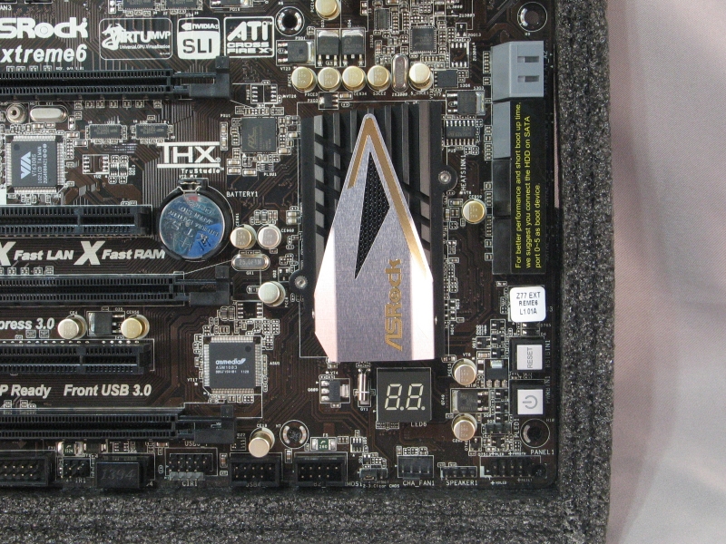
| SATA port detail | Front panel header detail |
The SATA port area is remarkably uncluttered, with just power and reset buttons sharing space with the SATA ports on the front edge. The front panel header pins are lined up along the bottom, along with the clear CMOS jumper and one of the chassis fan headers. As far as front panel headers go, we have three USB 2.0 headers, a Firewire 400/IEEE 1394 header, an IrDA infrared header, a floppy drive header driven by an add-in chip, a serial port header, and the HD Audio header in the back.
One gripe I have with this arrangement: the HD audio header pins are in the very back bottom corner of the board, which makes things awkward when the front panel jacks are usually at the top front corner of the case.
 |
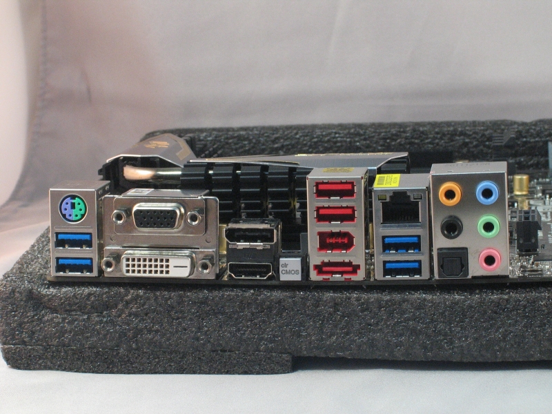 |
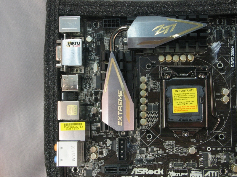
| CPU and IO panel detail | IO panel |
In another bout of uncommonly good sense, ASRock has put the 8-pin EPS power plug up on the top edge of the board, where it’s a simple matter to tuck the rest of the cable back behind the motherboard tray. If your case mounts the power supply at the bottom, be sure the EPS power cable is long enough to reach, or you may have to do some awkward/ugly routing. The power supply fan header, if you have need of one, is up here as well.
For the rear IO panel, we have an interesting port layout. From the top left, we have a PS/2 port, two USB 3.0 ports driven by the Z77 chipset, VGA out, DVI out, DisplayPort, HDMI, a clear CMOS button, two USB 2.0 ports, a Firewire 400/IEEE 1394 port, a eSATA port, 1000 Mbit Ethernet, two more USB 3.0 ports, and the audio outputs.

[…] ASRock Z77 Extreme6 Motherboard @TechwareLabs ASRock Z77E-ITX Motherboard @ Hardware Secrets ASUS Sabertooth X79 Motherboard @ Technic3D MSI […]
[…] ASRock Z77 Extreme6 Motherboard @ TechwareLabs […]
[…] MotherboardASRock Z77 Extreme6 Motherboard @ TechwareLabs […]
[…] ASRock Z77 Extreme6 Motherboard @ TechwareLabs […]
[…] ASRock Z77 Extreme6 Motherboard @ TechwareLabs […]
[…] ASRock Z77 Extreme6 Motherboard @ TechwareLabs […]
[…] and fix an improperly seated RAM module with barely a pause." You can read the full review here. "Other girl's luxuries are my necessities, so buddy, […]